We have already described in an earlier article construction regulations and the unavoidable requirement for testing a wing of a new design to destruction. The designer has achieved the desired strength data based on maximum weight, maximum speed, maneuvering speed, etc. Now it has to be proven in a real test whether the wing actually will stand up to the design strength.
The maximum load is not enough for testing purposes because a built-in reserve is necessary. Otherwise a slight overload could result in failure and possibly a death! Therefore the test load must be 1.725 times the calculated maximum load and it must hold this load for 3 seconds. And the whole test must be done at a temperature of 54o C (130o F) because the maximum load could occur in central Australia.
After that the test load will be increased until the wing breaks. Yes – each test will end with a fatal result. That is why the name is “Test to Destruction”.
A section leader at the DLR (German Centre for Air and Space Travel) said,
What we do to the wing here will never happen in the real world!
The destructive test for the wing of the new DG-1000 was scheduled for Friday the 14th of April, 2000.
 The test was done at the DLR field office at Stuttgart. The necessary equipment was available there: A high-ceilinged laboratory with a crane runway and a foundation piece for the wing root that would not simply be torn out of the floor!
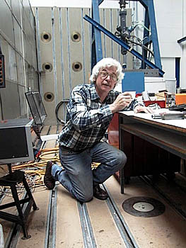
The test leader was again Mr. Reiter, known to everyone as Kloetzle (Blockhead) who carried out the procedure with much interest and factual knowledge. He is certainly the current official world master at destructive testing of glider wings. His destruction record includes everything from windmill driven electric generators to the enormous Cargo Lifter propellers. Kloetzle destroys everything!
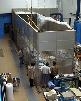
First a heat chamber had to be built around the test bed in order to bring the wing up to the required temperature. The chamber was open at the top and then later covered with insulating foil. A mobile was hung from the crane.
Didnt you build one as a kid with fish and birds on it?
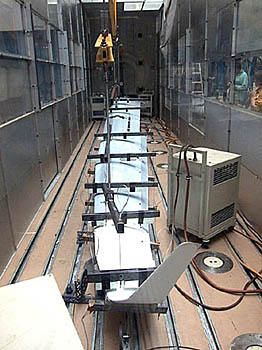
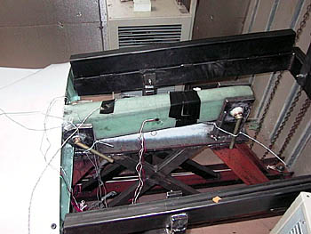
The loading arms were hung from massive steel beams and spaced out exactly to load the wing uniformly. The construction of this mobile is a difficult engineering feat in itself because the heavy beams should in no way load the wings themselves. Their job is to evenly spread the load on the wings in a good approximation of actual flying loads.
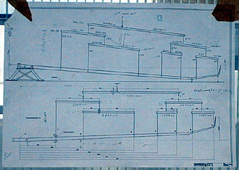 The mobile must work with the bending of the wing and at the same time load the wing as if it were flying.
So much for the preparation for the test. For me personally, the whole thing was an exciting event. One doesn’t see something like this every day and also I didn’t want to miss the testing to destruction of a wing on the first glider that I worked with. I asked my wife to buy two bottles of champagne and pack them in a plain brown wrapper so that we could sneak them back home again if something went wrong. But from the beginning I had not one minute of doubt that the experiment would be a success.
On the day before the moment of truth, I learned about a new side of my chief designer that I had never seen before.
Wilhelm, do you have stage fright?
Yes and No. Something can always go wrong. Murphy is always waiting in the wings.
Oh what a wet blanket! He could have at least put a brighter face on it. My trust in him went down some.
 A little more explanation is needed here about the test. At first the wing is stressed to its design load while it is cold. The testing crew simply call the maximum allowable flying load,
J = 1.
J = 1 means a load of 6.4g for the DG-800 for example. As a pilot you probably have never seen this maximum load because you would have had a lot of trouble keeping your head out of your throat and not becoming unconscious!
After a load of J = 1 (which requires the crane to be pulling with 1440 daN = 3240 lbs Force) the load is removed and the return of the wing to its original shape is carefully checked. This has to be the same as when the wing is tested hot, otherwise the wing was improperly tempered and further results are indeterminate.
Cold Test with J = 1
Click on the photo to enlarge it.
The Cold Test with J = 1 had already been done when we arrived in Stuttgart.
The bottom of the wingtip had bent up 2.3 meters. Wilhelm Dirks said that was the predicted distance. But can you imagine a glider standing flat on the ground and both wingtips pushed up 91 inches without anything happening?
Wilhelm also said that he had designed an especially light weight wing. For this reason, the results of that particular test were problematical.
After that we had plenty of time while the heating chamber was covered with insulated foil and heated. Sensors on various points and a recorder showed the rising temperature. The spar tang rose slowly in temperature because of its massive construction. The spar tang or the root end of the wing often fail in a test to destruction. An unbelievable amount of force is carried from the main pins through the spar box, spar flange and web into the wing. The main pins alone carry a force of about 20 metric tons! (22 tons force). The spar is held by standard main pins in a massive steel construction. If there were abrupt transitions built in, then there would be high stress concentrations, any one of which could be the point of failure!
The time went by slowly. We werent excited. No. In fact we stayed very cool!
And then the call from Blockhead (Herr Reiter): Were up to temperature. Lets get started!
Now we were in a hurry because the wing was beginning to cool down again. The protective cover was removed from the wing chamber. The visitors ran up the stairs to a safe height in the observation booth to watch the experiment. Wilhelm Dirks and Swen Lehner stood to one side at the spar tang station because that was the place most likely to fail. I ran around the booth with video and digital cameras trying to get the best angles to record the event.
J = 1.725 for 3 seconds, kept running through my head.
It became quiet in the hall. Nobody said a word. Only Kloetzle gave commands, Test begins.
The crane motor started again.
J = 0.5 – The wing bent up as if it were in strong turbulence.
J = 1, Stop. For three seconds there was complete silence and then the crane motor started again but in reverse.
We saw that already when it was cold but it held when hot even though the plastic loses strength when at this higher temperature. But it looked spectacular! Even the wings of an open class ship didn’t bend as much in a steep turn as ours did at J = 1.
But who ever flies at 6.4g ?
Loaded to J = 1.4
The return of the unloaded hot wing was compared to that when it was cold. The assistant looking at a comparison diagram on his scope, gave his, Okay.
Begin the test to failure. ordered Kloetzle.
What followed happened quicker than you can read about it. After 96 seconds it was all over!
The crane started again. I followed the winglet with my video camera as it was drawn up to J = 0.5 and then put it on the tripod because I couldnt stay there.
J = 1 – now we were in new territory and if something should break it could possibly be in the long axis of the wing and parts of it would go right through the wall where my camera stood.
J = 1.2 said Kloetzle and held his thumb on the switch for the crane. What a picture! Who has ever seen such a wing being loaded so much. And that was happening before my eyes!
At J = 1.4 the wing tip reached the upper edge of the 15 foot high heating chamber and was still going up.
J = 1.5 What are we doing here? Somethings not right!?
At J = 1.6 I was thinking that must be enough. A real wing would never be loaded to that point and no wing would hold that much anyway. Suddenly a crackling sound and then a crack! Now it must go kaput! More crackling – glue joints are breaking. It wont hold! Everything is going up the tubes! Lets think this over – lets see what we did wrong!
Loaded to J = 1.7
J = 1.7 – a loud crack – the wing shakes a little. Oh my God! Its going to break now for sure. Our beautiful new glider and Im standing there saying nothing! Kloetzle heard the crack and is staring so fixedly at the wing that he forgot to call out the loading for a moment.
J = 1.8 – did he say 1.8? But thats enough! Stop now! Its enough! Three seconds, please, only three seconds! Stop the damned crane! But Kloetzle, this fiend, keeps his thumb on the switch!
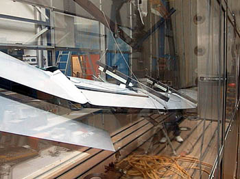
J = 1.—- A thunderclap crashed through the room. A great wave ran the length of the wing and broke it to pieces. That was it for the beautiful wing! The heavy steel beams of the mobile tumbled wildly through the high temperature box, especially the apparently undamaged outer wing in its cradle because it was catapulted out of its spar-pocket in the inner wing.
Its dead quiet. I stopped my camera mechanically and looked up. The onlookers still were staring at the broken parts as though they could not believe what they had just seen. Some were standing forward against the railing and some were standing fearfully back against the back wall.
What actually happened here? I asked myself. I noticed that at the moment I could hardly speak and could only say two words to the test leader, How much? “I don’t know,” said Kloetzle, “we have to look at the recording. About 1.8 – enough in any case.” It was enough, he said? Even though everything was broken?
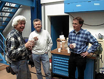
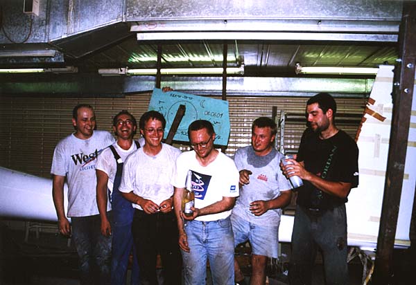
Wilhelm came to me and apparently he couldnt speak either. We just shook hands silently. Slowly the others began to move about. First a cheer and then my wife pulled out the champagne. It had become warm and Kloetzle asked with raised eyebrows why we had not let him cool the champagne beforehand. He could have cooled it down to the temperature of liquid nitrogen, -196 degrees C! (-321o F). No problem for the DLR!
Wilhelm went into the still hot test area, pulled the cork and let the champagne fountain spray over the broken parts of his wing. Was this a kind of reparation to the sundered raw material?
Twenty paper cups like we use in the factory for resin were found and while we were filling the cups with champagne, a technician came and with an almost military tone reported:
“The results of the test gives a breaking point of J = 1.95.
The recorded load 3 seconds before the failure was J = 1.89!
Congratulations Mr. Dirks!”
Wilhelm beamed with pleasure because this is the absolutely optimal result.
It means we have a 10% reserve that we can use later for various niceties such as more water ballast, greater gross weight, etc. We would not have wanted more reserve because it would have meant the wings were unnecessarily heavy and more expensive to produce.
10% is optimal. It could not have been better!
The next bottle of champagne went on our second designer, Swen Lehner, but he declined with a nod, Thats Wilhelms wing.
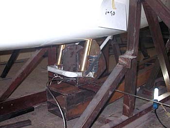
Actually, Swen had reason to be proud too. He had just come from Slovenia where he directed the building of his prototype fuselage for DG-1000. There was also a load test of this fuselage which involved a rather complex structure. The main wheel has to rotate so far forward that we do not need a nose wheel. It cant be placed farther forward because the rear seat pilot sits there and we werent sure if that design was correct.
The landing gear was also tested by applying a force of several tons from underneath through a massive structure of steel beams to simulate a hard landing. It held without any deformation. We could leave it as is in the glider and fly the prototype as production number 10-001. Only the wing had to be tested to destruction. The other components would be left in peace until their integrity could be assured.
 There were several of our employees there with proud looks on their faces!
Especially some of those from the crew that had built the wing took time off to witness the show. One of them spoke to my wife in the temperature chamber. He pointed to the spar tang which is known to be especially critical. We built that. Look at it, not even a hair-line crack in it. It held completely.
Bravo! And that goes for all the people who worked on it!
That was an excellent piece of work because, in the end, they built the prototype wing to the same standards as in subsequent series with which they will have much more experience.
a happy Team!
 |
Finally, as we were driving back to Bielefeld, my wife said,
That was something that an ordinary mortal doesn’t see every day.
Video clip
 |
Testing to Destruction of the DG-1000 WingCamera-inside: 22 MB Camera-outside: 15 MB |
– friedel weber –
24 hours after the “Big Bang”
translated by David Noyes, Ohio
Load Tests on the Fuselage of the DG-1000
A less spectacular test than the destruction test of the wing was undertaken one year later in the main temper chamber of AMS-Flight in Slovenia – this was the load test of the DG-1000 fuselage. As it happened I was on a gliding holiday in Lesce and took the opportunity to see this important test.
The main focus was not the destruction of a part – it was merely a case of doing a series of tests in the process of certifying the glider. This was done so we could calculate the highest loads on the fuselage that could be expected according to the certification (“J=1”, you know what I mean). The fuselage then had to bear loads of one and a half times this calculated value without any signs of deformation.
Just to let you know straightaway: All tests were successful – nothing broke – or did it? – Various steel cables and ring pairs broke and mounting flanges on the pulleys were bent, in particular, when we tested the release hook. The forces that our “poor” fuselage had to endure were enormous.
And to make it even more exciting all tests took place in the temper chamber at 55 °C. I felt really sorry for our engineer Swen Lehner and the crew of 5 AMS employees – and the local mineral water factory made loads of money!![]()
Among other things we tested the following:
- Full rudder deflection at maneuver speed (185 kph). Here, J=1 equals the vertical force of 90 daN and a lateral force of 215 daN (one Dekanewton – daN – is the equivalent of 1 kg of force).
- Simultaneous rudder and elevator deflections at 305 kph – (VNE + 10 %). Here, J=1 equals a vertical force of 435 daN and a lateral force of 105 daN.
With these loads things will get bent if the fuselage is fixed with its lateral wing mountings in a heavy steel mount. Have a look at the two photos between “J=0” and “J=1” which were taken from the same point of view. However, the force exerted at J=1.5 was 652 and 157 daN!!! (No need to mention that, in accordance with the glider manual, full control deflections are only allowed up to maneuver speed…)
 Maximum pressure load of the vertical stabilizer: In this case, at J=1, a force of 551daN acted on the vertical stabilizer from above.
 Maximum pressure load of the vertical stabilizer: In this case, at J=1, a force of 551daN acted on the vertical stabilizer from above.
- According to JAR 22, at J=1, in an “ordinary” heavy landing the undercarriage of the DG-1000 would be subjected to a vertical force upwards of 1560 daN, combined with an additional force of 901 daN from the front to achieve a resulting force which acts at an angle of 30° forwards and upwards.
- One major aspect of the undercarriage stability needs to be additionally calculated and confirmed:
The undercarriage needs to cope with a landing impact at a sink rate of 1.5 m/s without sustaining any permanent deformation.
After all, a sturdy undercarriage is the best protection against back injuries.
The best way to achieve this is by using an optimal spring / wheel ratio, i. e. the ratio between the distance when compressing the undercarriage springs and the tire’s cross section height. In a heavy landing like this, the tire is compressed to the rim, and as every additional millimeter of spring compression is vital for this requirement, the DG-1000 is fitted with such a big wheel. This also has the effect that the ground run in this glider feels very comfortable. - To simulate a slipping landing a vertical force of 0.5*1560 daN had to be combined with a lateral force of 0.3*1560 daN.
- Next, we “tortured” the mounting of the belly hook: It was subjected to a breaking load of almost 2300 daN forwards and at an angle of 75° downwards respectively, even though there is no weak link stronger than 1,000 daN.
- At last we tested the effect of a purely lateral force which at J=1 equals a force of 765 daN.
I have often asked myself if these tests aren’t going a bit over the top, but this is how the certification rules are.
It was in any case very exciting to watch and at the same time very reassuring that everything stayed in one piece. If you buy a modern glider, certified in accordance with today’s rules and regulations, you can without a doubt rely on the fact that you get a glider that will usually survive any maltreatment (whether caused by carelessness or mistake) without any damage.
– Of course this is NOT an invitation for you to test out the limits of the glider yourself. These load and destruction tests are always very theoretical tests. In a real-life situation however there may well be a case where even these very high load limits are reached – and one should never attempt to experience these limits!
– friedel weber – June 2001 –
Translation: Claudia Buengen
the test crew
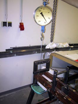 …. and at last we made a load test for the head rest in Bruchsal.
It must be strong enough for 135 Kilopond.
Former Destruction Test in Japan
This is a nice Story from Mr. Ooishi, who is the main translator of our Japanese Page
Dear Mr. Weber,
Enclosed please find a new pdf file. It was an interesting subject for me, as I had a same kind of experience to yours about twenty years ago:
There have been some Japanese built two seater types widely used in many gliding clubs in Japan during 60’s and 70’s. (Importing foreign built gliders such as K-7s and ASK-13s were difficult because of low currency exchange rates.)
It was amazing however none of these Japanese types had type certificates.
They each are regally and actually “one off” and independent airworthiness certifications were given, as to my best knowledge.
There was one unused airframe (an unsold stock) and it was decided to give it a loading test.
The test was carried out at an experiment facility of a technical university near Tokyo. I think it was one day in 1983 and was a very cold winter day.
A similar arrangements to the test of DG-1000 wing were laid down in the facility. There were many gliding pilots and mechanics as well as academic researchers attended and watched the test.
At first, less than its max load (about 4.0g, as I remember) was applied to its wing. It held. Then there was an announcement to increase the load to the certified maximum. The “Mobile” showed a slight movement upwards.
At the very next moment, with a loud bang, the outer panel of the wing snapped at just outer its joint to the center section. The load applied was only 5 gs.
I remember there was a curious calmness wrapped the whole place just after the bang, like as you mentioned on your article.
Then we felt a deep voiceless anger because so many of the pilots had been flying in the type and had quite often experienced bad over-speeding in winch launching, or in some cases, carried out basic aerobatics for many years.
Next, a wing from a crashed K-8 was tested in a same manner. It was amazingly held to its terminal load, and above that, only a hardware holding a main pin at the center of the wing buckled. The wing still looked in a good shape.
What we have learned: “Nothing is fearsome if you know nothing.”
After the experiment, the authority advised to all inspectors not to certify the same type any more. Since then the numbers of German made two seat gliders begun increasing rapidly in Japan.
—
This was a very good article. I really enjoyed to translate it.
Naoaki Ooishi