At the symposium on aerodynamics and glider manufacture at the DLR in Stuttgart there were extensive theoretical opinions presented about the future of Sailplane manufacture. The main considerations were new materials and their methods of use and also questions of performance increases in the future. The papers by the director and his colleagues, that mostly had to do with aerodynamics and new airfoils, were particularly interesting. The current situation is characterized by the fact that the performance of modern gliders has become very similar. A significant increase in glide ratio and reduction in minimum sink is not guaranteed even in brand new machines. That means that the manufacturer of very expensive newly developed aircraft models is saddled with a very high risk. He cannot be sure that he will succeed and surpass the models already on the market. Because of this, the “performance contest” of the glider manufacturers has increasingly moved to themes such as comfort, safety, and motorization etc. The kind of quantum leap in innovation that occurred with the advent of fiberglass technology is not seen at present. What can we expect in the long term and what is already possible today?
Boundary layer suction:
Boundary layer suction is a revolutionary concept which has been under development for some time by Loek Boermans at the Technical University of Delft. Mr. Boermans is one of today’s most active developers of new airfoils for gliders. He is making use of his new concept of boundary layer suction by putting a 1.5 mm wide slit along the entire length of the wing about 30 cm forward of the trailing edge. During flight, a pump in the fuselage sucks air evenly through this slit at the point where the boundary layer begins to become turbulent. That’s it! No flaps are needed on this airfoil because totally laminar flow exists at all speeds. Glide ratios of 100:1 should theoretically be attainable with large spans; glide ratios of 80:1 should be reached without any further problems. Such a glider would not need to circle, rather it would fly almost entirely in dolphin mode with the expected effect on the over-all speed.
But there are a couple of small problems that have to be solved first: The long slit destroys the box construction of the wing. And on the inside of the wing, a continuous connection between the top and bottom surfaces of the wing is no longer possible because the pumped air needs to flow into the fuselage with no turbulence. The last third of the wing is attached only by the skin of the lower wing surface and at the same time has to be strong enough that the wing can be carried by the trailing edge.
A turbine pump must operate in the center of the fuselage like a vacuum cleaner. Two turbines, one in each wing, are not an option. If one turbine should fail, one wing would revert to a glide ratio of 25:1 and quickly put the glider on its back! The turbines for a 25 meter glider would use about 500 watts continuously! The electric power can only come from having a large part of the glider covered with solar cells.
Technically that is possible but very, very expensive and delicate. What would happen to a flight in the waning hours of daylight or under heavy cloud? A buffer battery can not last long at the required power consumption! Finally, would such a glider still be considered a glider under the rules of competition? In any case, it requires a continuous energy source, namely the sun.
Boundary layer suction is without a doubt a fascinating concept. Perhaps in a few years a prototype might be built, which would be of huge benefit in advancing the technology. It will certainly be a long time before a sailplane manufacturer brings such a glider onto the market!
Winglets:
On the other hand, there is another possibility that is used for all modern gliders and can markedly improve the flight capabilities: Winglets!
 Loek Boermans at the University of Delft, whom we have already mentioned, says that winglets are a relatively inexpensive method for improving performance of even older gliders.
A significant portion of the total drag of a sailplane is induced drag. The airflow around the airfoil creates significant drag (as calculated from the polar) only with an airfoil of infinite span. Span-wise flow increases towards the tip due to higher pressure on the bottom of the wing and lower pressure on the top of the wing. The tip vortex decreases the lift contribution near the tip to nothing. Large spans and high speeds reduce this effect markedly. This has led to the development of winglets for the standard class in which a significant portion of the drag is induced drag. Winglets reduce the drag to the same degree as an increase in span equivalent to the height of the winglets. Since practically no lift is generated at the tip, the winglets can be vertical. Therefore the glider does not fall outside of its competition class and the handling on the ground is no more difficult.
The winglet must be bigger as the span becomes smaller because with smaller spans the percentage of induced drag becomes larger. There is a limit to this, of course, because at high speeds the winglet is no longer necessary since the percentage of drag which is induced drag becomes smaller. In high speed flight the winglet itself produces undesirable drag when it is too big. Therefore there is an optimum compromise in size for the winglet depending on the span and airfoil.
Conclusion: if winglets are available for your glider from the manufacturer, you should make use of them. There is no more effective a way to increase performance at a reasonable cost. If you don’t have winglets, check and see if you can get some made for your glider. In contests, winglets are a “must”. And circling in thermals goes better with winglets……as if you were on rails!
By the way, winglets are available for all new DG sailplanes including the DG-800 in the 18 meter configuration.
Unfortunately it is not possible to build winglets for DG-400:
The additional weight at the wing tips may cause fluttering and that is dangerous!
Flaps:
There is not much new to say about flaps and they can’t be added, anyway. In general, the special airfoil required for use with flaps gives a worse performance than a non-flapped design when the flaps are set at zero angle. When one tries to use one airfoil for both types of wings, one has to carry out very careful wind tunnel studies. Otherwise one gets a more or less bad compromise.
A pure flapped glider is, of course, better than an unflapped ship in high speed flight (using negative flap settings) as well as in low speed circling (with positive flap settings).
– W. Dirks –
Newer developments on this subject:
While at the world’s competition, I had the opportunity to have a long talk with Loek Boermans. We talked an entire evening about many aspects of aerodynamics.
Boundary layer suction:
At that time a new concept was worked out in which it wasn’t necessary to cut a continuous slit in the top of the wing. Instead of that, a laser would cut a line of many tiny holes; 4 per square millimeter. The air would be pulled through these holes. One would also use in this case more “normal” profile which, if the suction were lost, would give reasonable performance. This would allow the use of 2 blowers in the wings that would prevent an immediate roll in the case of a loss on one side. The exhaust air exits at the wing tip slower than the airspeed of the glider. In no way would there be any thrust as from an engine-driven propeller.
The whole concept is just in the talking stage and not yet feasible even for the most innovative glider manufacturer.
Too bad; that would be a challenge for us…….
Winglets:
Loek Boermans repeated the importance of the commonly-held opinion that a standard class glider without winglets is for him unimaginable. However, there are several examples of winglets on the market that he thinks are not right. It’s not enough to simply lengthen the wing and then bend it upward. A special winglet profile has to be developed.
A positive advantage should certainly be noticeable with winglets for an 18 m wingspan and he is happy about our apparent success with the DG-800.
Winglets for a 20 m span wing should also be possible. However, the chord would be smaller. That would just look like a filigree at the end. Winglets for spans greater than 20 m (examples: ASH 25 and Nimbus 4) would be superfluous and probably would do more harm than good according to Boermans. The only possible advantage would be that the effectiveness of the wing dihedral would be increased which would help the thermalling characteristics. At the same time the drag would increase because of the longer leading edge without an increase in lifting area.
He had an interesting opinion about the doubly bent up wing (Ventus): such a glider flies very well. But when the wing touches the ground during a landing, the whole outer wing lies flat on the ground which could more easily lead to a ground loop.
(That is the reason, why the bend of the DG-1000 outer wing is so great that this wing will not lie on the ground. Furthermore the wheel under the bend gives another ground distance.)
I offer these opinions of one of the best known glider aerodynamicists without comment.
By the way, the richly-enjoyed Bordeaux wine was very good!
– friedel weber –
(translated by David Noyes
and edited by Beth Langstaff, Ohio, U.S.A.)

.
Measurement of the Airfoil-Drag of a DG-800B
Fuselage-Wing Interference
We currently use laminar profiles for the wings. The relative wind and the air surrounding the airfoil have to enable a laminar airflow. It is easy to see the opposing effects when someone looks at parasite drag.
Well, the airflow is nowhere close to be smooth within the first 3 feet of the wings measured from the fuselage.
It’s more or less turbulent. Therefore the wing profile that is being used in that area is simply wrong. It is useful to set up the wing with a different angle of attack within the first few feet and use a profile that is designed for turbulent airflow. Then, after about 2 or 3 feet the profile should be changed to a laminar profile.
It has to be mentioned that almost everything that deals with aerodynamics does come with a bad side effect and one has to live a live of compromises:
A modified airfoil for example does not warn the pilot ahead of stalls. The warning results out of a disrupted or separated airflow alongside the inner part of the wing that moves on to the elevator and shakes it – making it known to the pilot.
A warning of that kind is very weak with modern airfoils. It will even become less noticeable in case of a modified profile. Such an aircraft will, if flown very slow, be in a stalling situation without the pilot’s knowledge.
Therefore it is of great importance to have a very “gentle” airfoil in case of modifications.
There are no extra costs for such a modification, but the original mould has to be different. Therefore it is close to being impossible to change the current models to the newly learned settings.
The results of that change are not too drastically. Although it’s hard to prove that, because measurements can only be made by calculations and not in real flight testing.
To our knowledge the ASW 27, ASW 28, DG-1000 and the Discus 2 are already equipped with wings corresponding to the new data, but it was too late for the new aircraft of the 18m class.
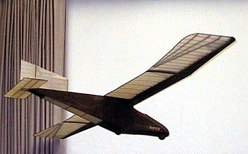
“Vampyr”, Wasserkuppe 1922
“The Beauty and the Beast”
Aerodynamic today and yesterday:
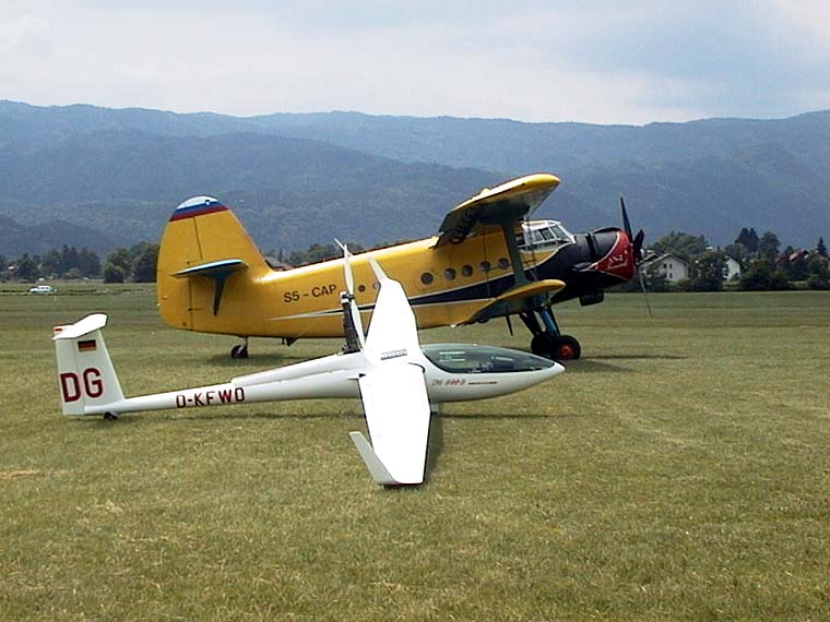
DG-800B in front of Antonov AN 2
L/D ratios in gliders
It is almost impossible to describe the performance of a glider using just the maximum glide or L/D ratio. For this reason one of the glider manufacturers stopped quoting L/D ratios several years ago.
We agree that a single number says very little about the actual overall performance of a glider and prefer analyzing the differences in performance of different gliders by comparing them in flight. After all, with this method you can test the glider through the range of the complete polar curve. You might not get any absolute values but a good comparison to the other glider used for reference.
However, our customers would like to see a maximum L/D ratio figure, so the following might explain that.
In general we publish a calculated polar curve and a maximum L/D ratio. This calculation is based on the profile polars which have been measured in the wind tunnel. The induced drag, the form drag of the fuselage, and the interference drag are added to the profile drag values of wings and elevator. Unfortunately not all these drag values are known, and the wind tunnel measurements might not fully reflect reality either.
Therefore the engineer will compare calculations and measurements on previous gliders and estimate a correction drag value.
It is also important to interpret the L/D ratio figures correctly. Based on the assumption that the correction factor wasn’t “reduced for marketing purposes” the glider will reach the quoted value in optimal conditions – i.e.:
- taped correctly
- max. wing loading
- optimal c of g position
- polished and totally bug-free
- in absolutely calm air, i.e. no turbulences (which means nowhere near clouds)
- with closed and locked undercarriage and engine doors and airbrakes (all flush)
- without corrective control movements
- in ISA standard atmosphere conditions
Calculating polar curves in a test flight is very difficult and prone to errors. There are for instance polar curves for the same glider but from different years which are not identical. Particularly the best L/D ratio changes significantly due to minute measuring errors. For example a difference of only 1 cm per second in the sinking speed causes an L/D ratio difference of 1 point. Measuring errors in a comparative flight can however be much bigger.
So you see that the quoted L/D ratio is normally merely a theoretical value that you shouldn’t use for your final glide calculations. In real life you should use a value of roughly 4 – 8 % below the theoretical best L/D ratio.
– friedel weber & w-dirks –
translation by Claudia B